
Topping It Off
Roof trusses are set & roof sheathing is installed to complete the construction shell.
Read on to learn about the process, watch the drone video & get close up with the plans & construction details.

Truss Installation
Roof trusses are pre-engineered to precise specifications & dimensions per the architectural plans. They are designed to handle code-minimum design forces under the most extreme conditions.
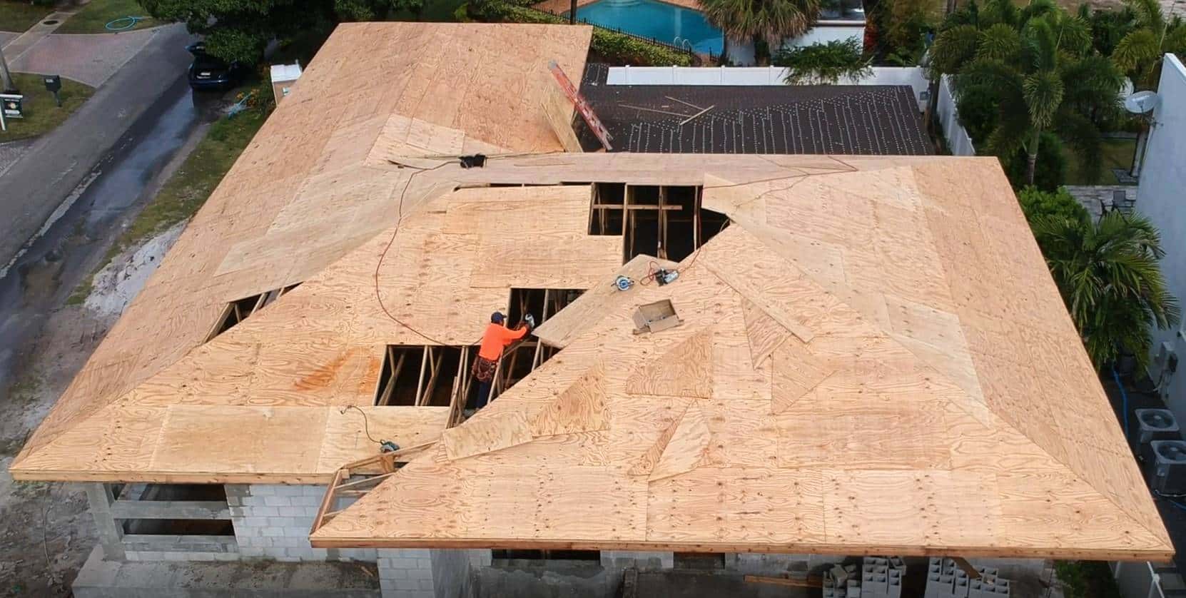
We pick up the story with the trusses installed & the roof sheathing (plywood) under construction.
The Truss Engineering
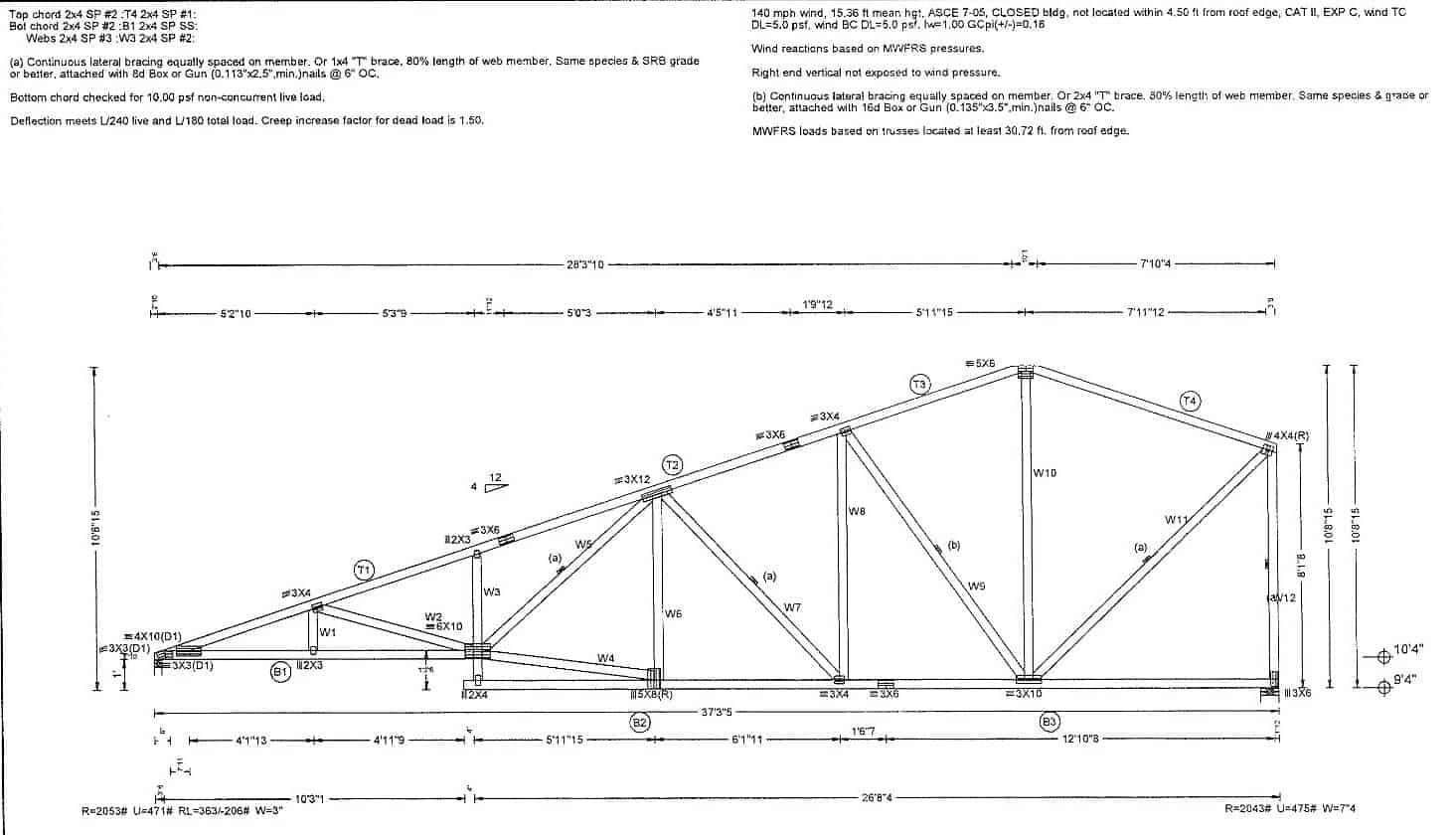
This is a sample of truss engineering. Each truss in a pre-engineered roof system is computer-designed to exact specifications and fabricated by machine to meet the design requirements.
This example illustrates:
- Wood members, types (top left)
- Design criteria (top right)
- Reactions for straps (bottom left)
- Dimensions & internal connections
Truss engineering is reviewed and certified by a professional engineer & approved by the architect. Building inspectors will review both the plans & installation for conformance to the code.

High Wind Uplift Condition
These trusses overhang the front of the building and create a high uplift wind condition.
This condition is accounted for in the truss engineering, and the project engineer then specifies the appropriate tie-down straps to secure the trusses in place.
The below photos show the straps used for these trusses. There are 2 straps per truss, one on each side.
In the engineering plans below, item 4 shows the details of each strap required and the corresponding product approvals that certify the product.
Truss overhang roof straps to the below bond beam side 1
Truss overhang roof straps to the below bond beam side 2
Close-Up
Take a closer look at the roof truss & sheathing installation.
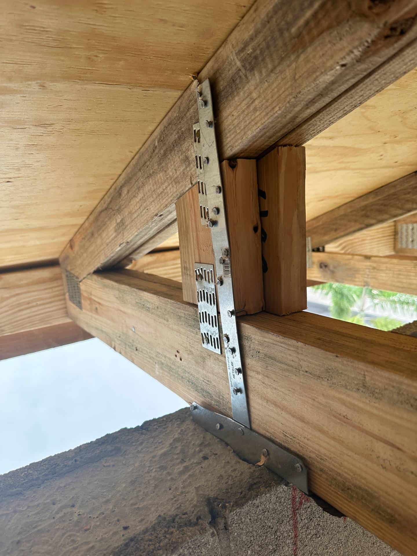
Roof Truss Straps are embedded in the concrete beam when poured and nailed to the trusses using an engineer-perscribed set of nails.
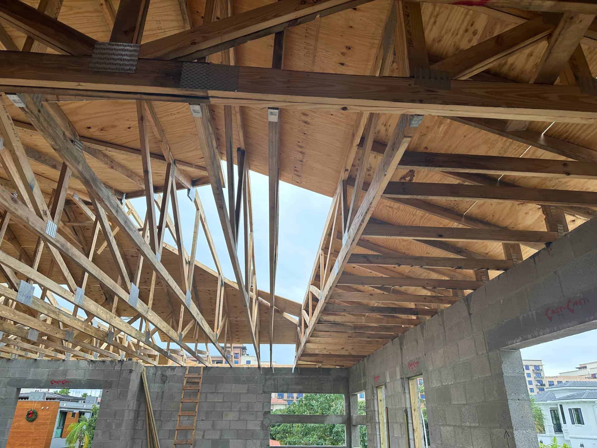
Trusses that support other trusses are called ‘Girder Trusses’. In this example you can see a girder truss holding ‘Truss Jacks’ – series of smaller trusses to complete hip roof framing.
There’s a second girder truss in the forefront of this image holding other trussed. This girder is two members thick to handle those larger loads.
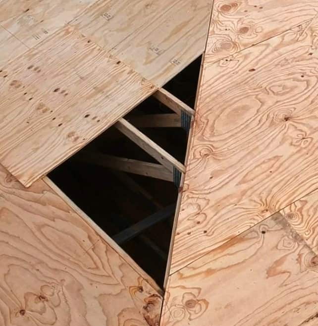
Roof sheathing is supported along all ‘strong’ edges by half of a truss member at all times. These are the end sides in the direction of the wood grain.
This process is described on the plans (see item ‘3’ in the plans below).
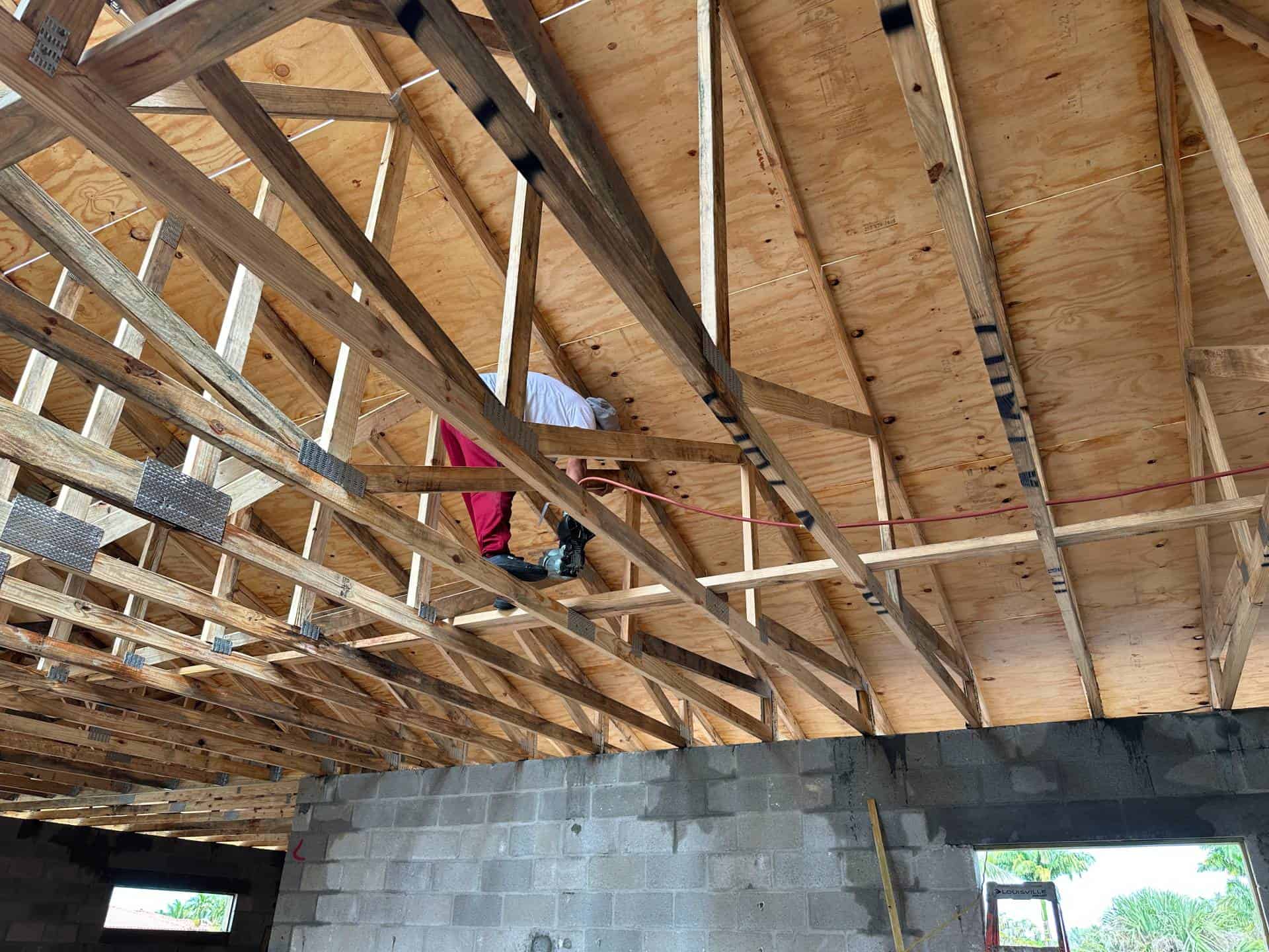
Bottom chords of trusses are supported laterally by truss bridging – Strips of lumber perpendicular to the trusses at intervals specified by the architect & per code.
This helps keep the trusses in place during construction, use, & prevent cracking of ceiling drywall.
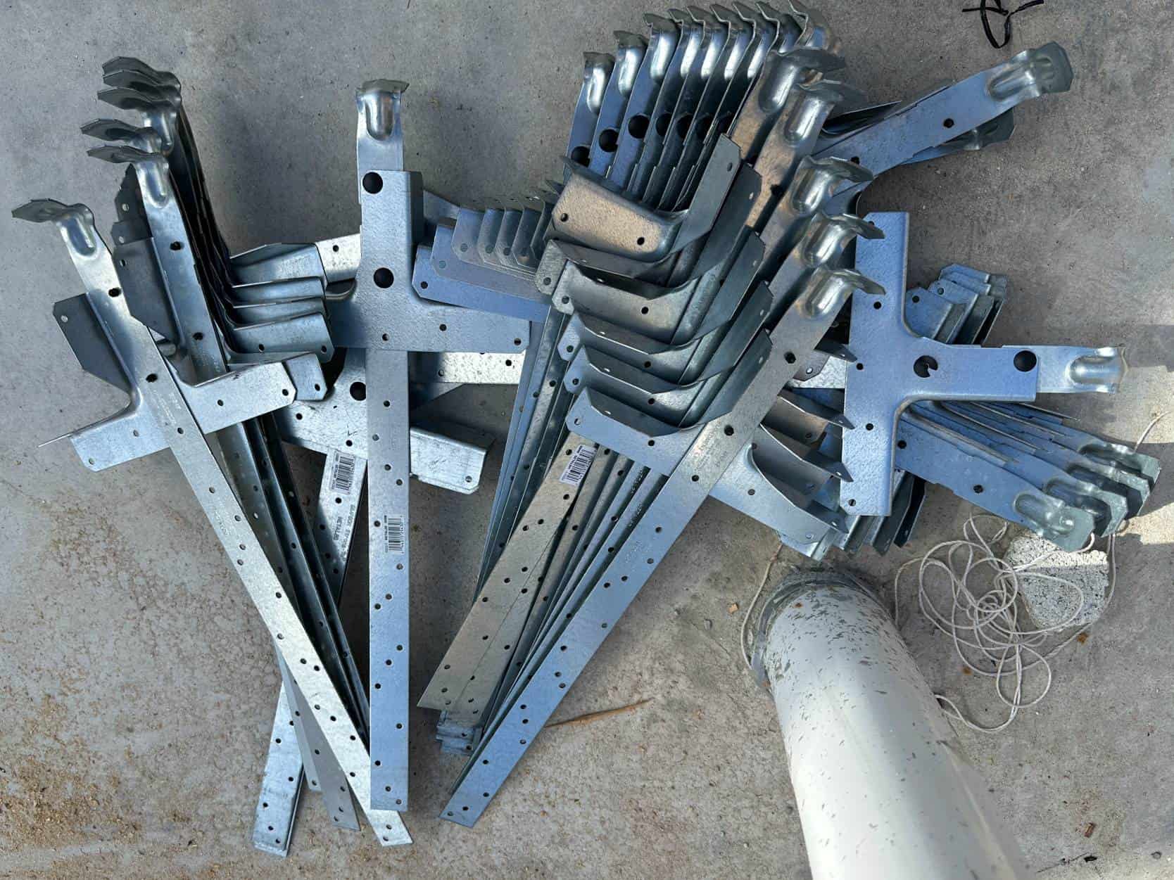
These are the truss straps used to secure the roof trusses. You can see there’s a considerable portion below the truss seat that embeds into the concrete beam and hooks the steel reinforcing.
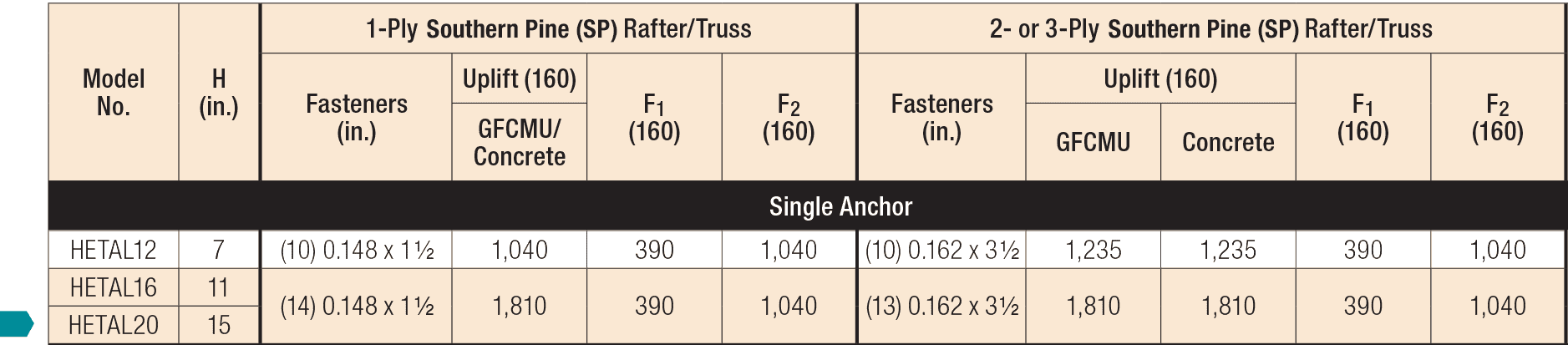
This product is a Simpson Hetal20 which also carries a Florida Product Approval # FL11473. The strap capacity table is shown below which is matched to the uplift requirements in #3 in the engineering below to produce the requirements in #5.

Drone still of the roof truss & sheathing construction in progress. See the video below for the full areal fly-over.
Technical Corner - Plan Tutorial
The Engineering Behind The Plan
Learn to read the construction plans
Plan Page: Truss Engineering
- This area is the lower roof for the 1-story portion of the structure. Those trusses are defined on a similar page.
- This overview illustrates direction of waterflow, roof hips, and general information about the roof & elevations.
- Wind affects different parts of the roof with different uplift pressures. These tables & charts illustrate the uplift forces and roof areas for those forces along with plywood nailing requirements. These numbers are used to calculate uplifts & strapping described below.
- This is the roof truss strapping schedule. Each strap is calculated based on the uplift requirements to #3 above.
- These callouts illustrate which strap goes to which truss along the entire perimeter.
- This illustrates a girder truss, a truss holding other trusses as seen in the close up above.
- This illustrates the method, direction, and details of adding the roof sheathing to the trusses.
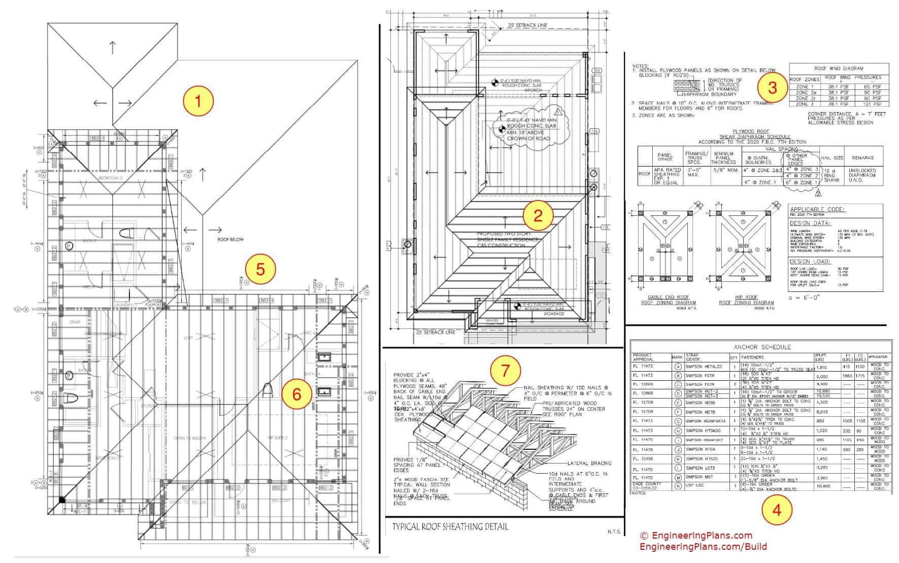
Roof Truss Blueprints. Click/press the photo to enlarge
Quick Clips From The Field
Watch breathtaking fly-overs of the roof sheathing installation & truss framing
What's Next?
With the building shell almost complete, we’ll be showcasing the many building components and finishes that go into the building design, and in a whole new way.
You see the roof sheathing being finished with this black paper – That’s 30lb roof felt paper nailed down a prescribed way as required by the building code. Those large washers are ‘tin tags’ that help in holding the felt down in high winds See FBC chap 15 for more. This was done now to protect the roof sheathing and below from water.
There’s more to the roofing to come, Then we move on to fully waterproofing the building to begin interior construction.
