
All Tied Up
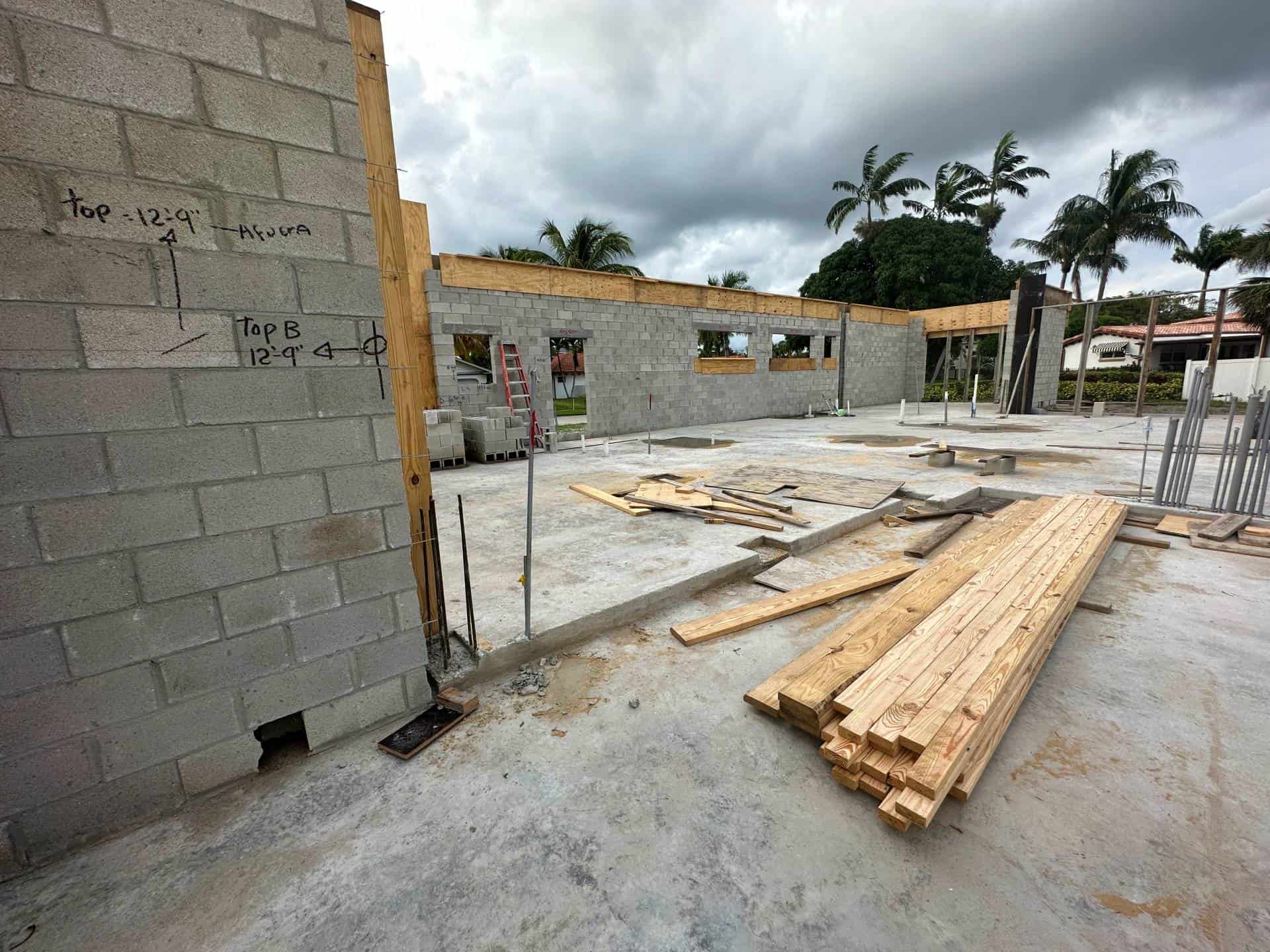
With the first floor masonry walls in place, it’s time to tie them all together.
This is necessary not only to give the masonry walls strength, but to prepare for floor trusses, the second floor, and to create the finished, all tied together box which becomes the house shell.
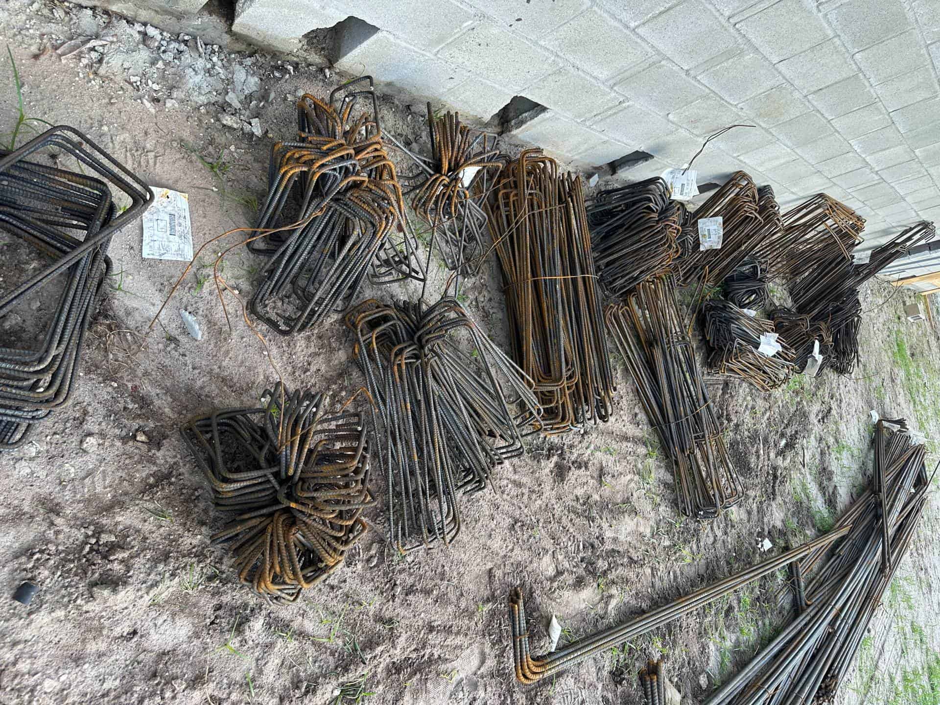
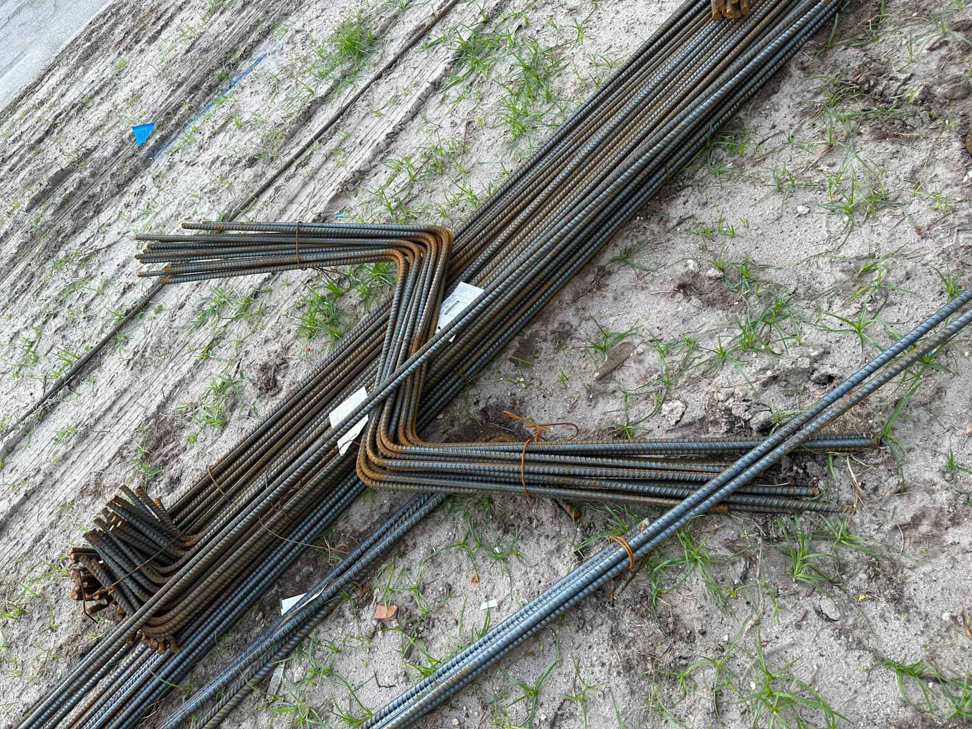
Steel Delivery
The reinforced masonry cells, columns, and beams above will be poured with concrete.
Before that can happen, an intricately designed web of steel needs to be formed inside the openings, then formed with plywood to get ready for the big pour.
Here we see the steel reinforcing delivered to the job site in preparation for framing.
Each piece size is for a different need, designed by the structural engineer and counted & ordered by the GC for the installers.
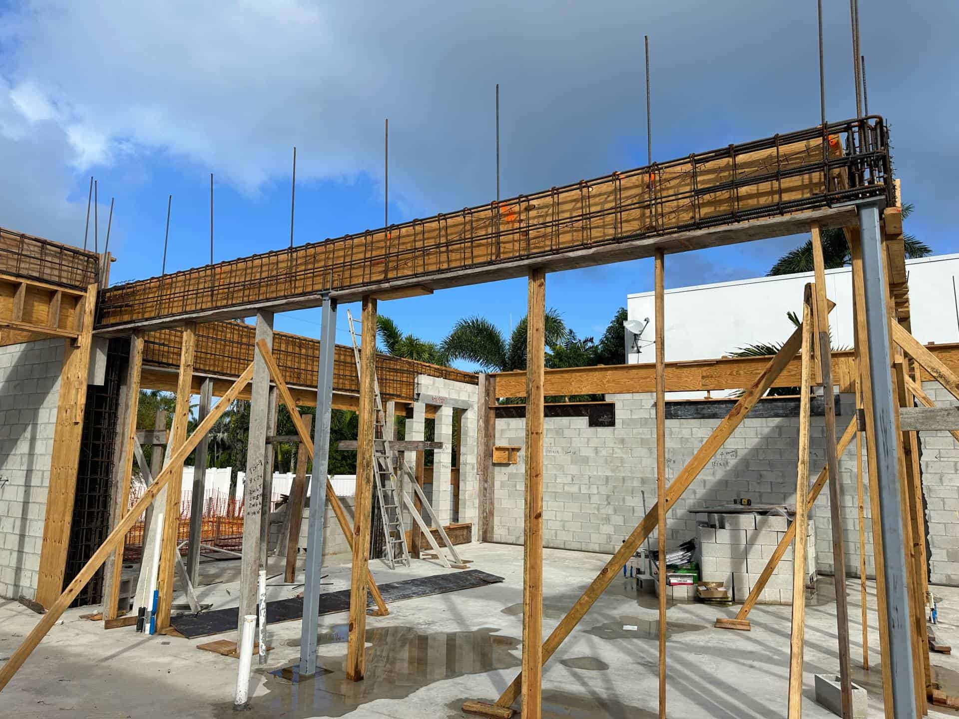
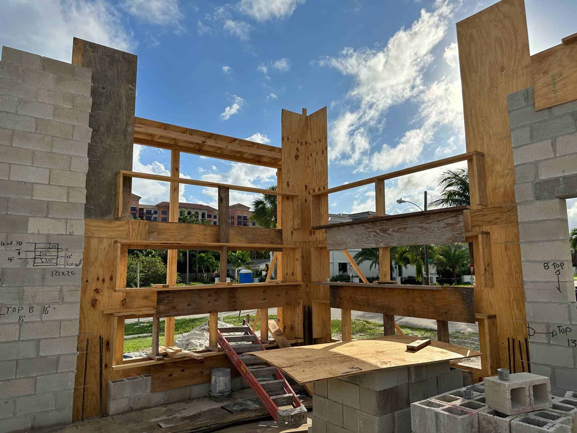
It Starts Like This
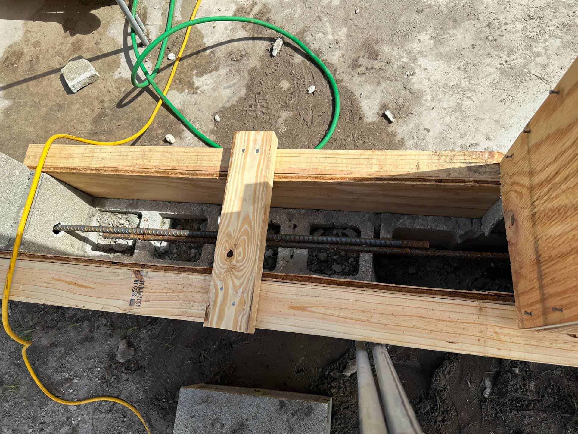
Wood is delivered to the site along with the steel reinforcing so the framers can build the steel cages that go inside the beams & columns & wood can create the form for the concrete.
Here we see the masonry walls getting lined with the plywood forms and the site prepared for the next steps below.
There’s a lot of prep work that has to be done, inspected, and approved before the concrete can be poured.
Let’s take a closer look.
Grab & Spin This 360 degree image of the tie beam - tie column framing in process.
Pinch or scroll the mouse wheel to zoom in/out
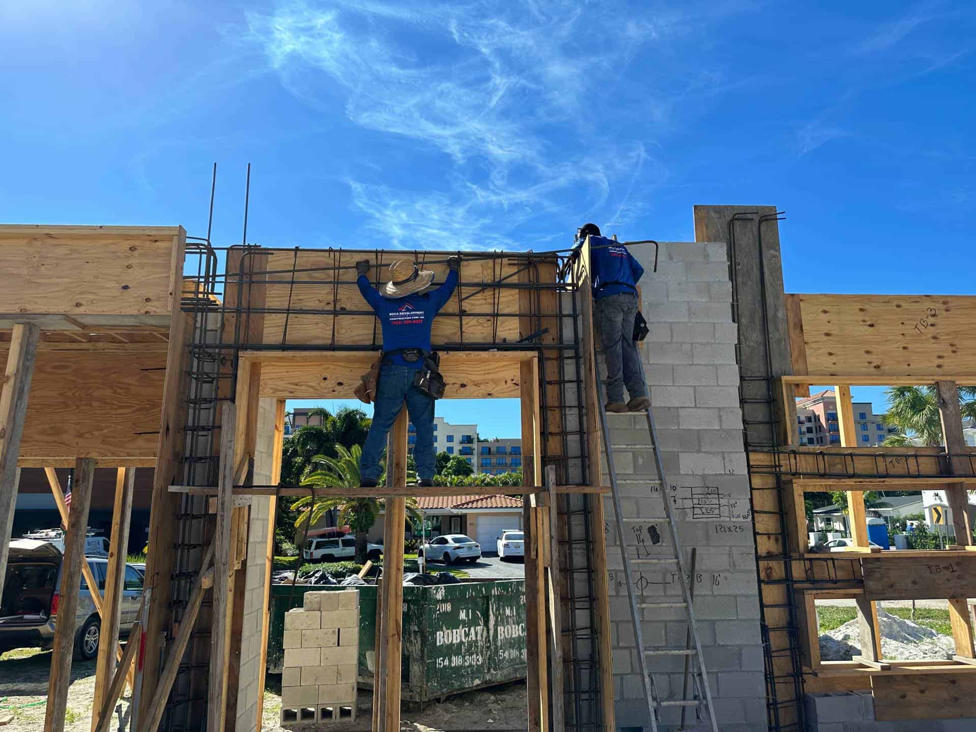
Time Sequence 1: Front Corner Windows
An intricate framing of woodwork forms these corner windows. This framing also serves to ‘tie’ everything together.
Steel reinforcing is then added to the cavities created by the wood framing. When poured with concrete, the steel will do the work to hold everything together & prevent cracking under the toughest of design loads.
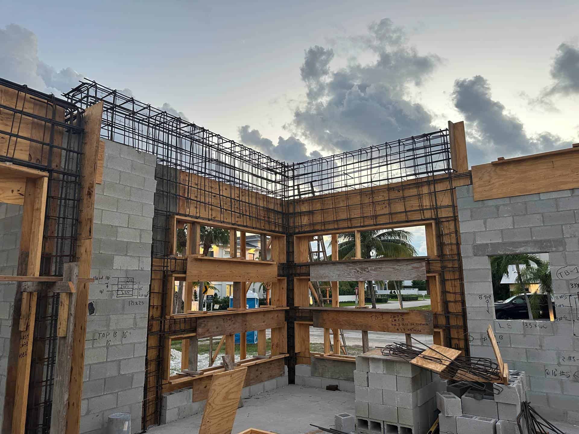
A giant steel cage is formed above the windows to provide support for the second floor and roof above. It’s poured solid not only because of strength but because creating two beams would be more labor & concrete work than it saves.
Time Sequence 2: Front Entryway
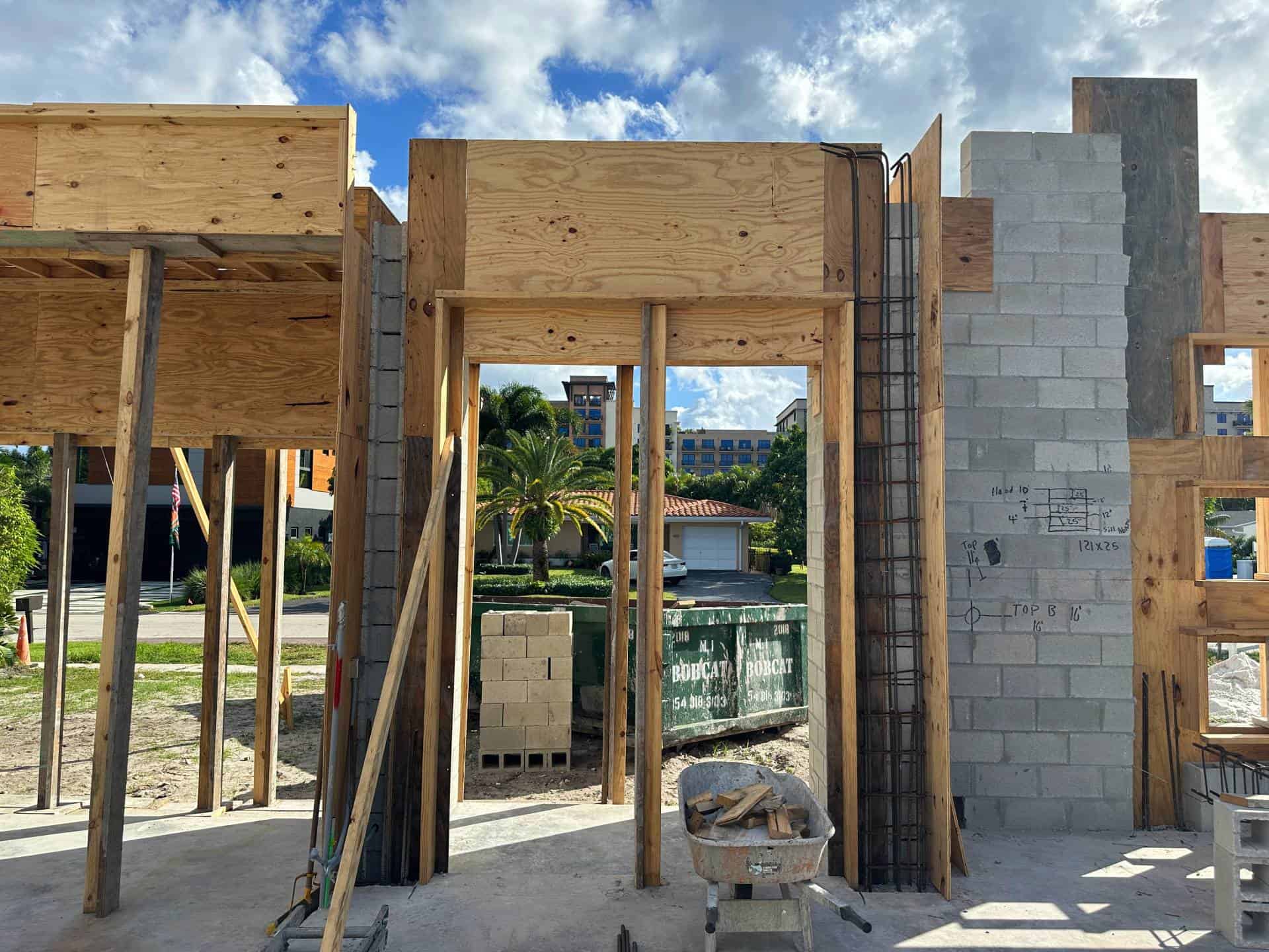
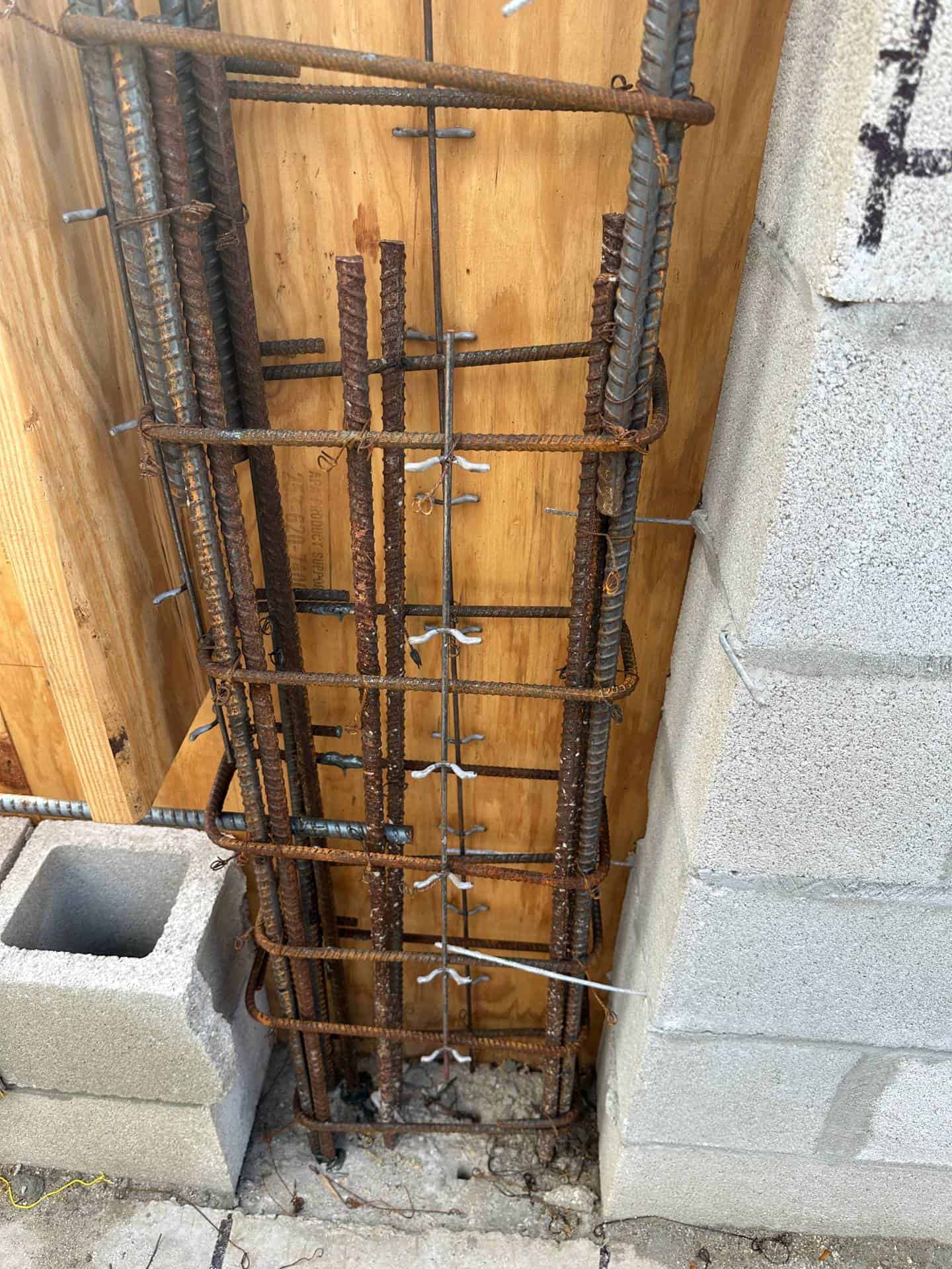
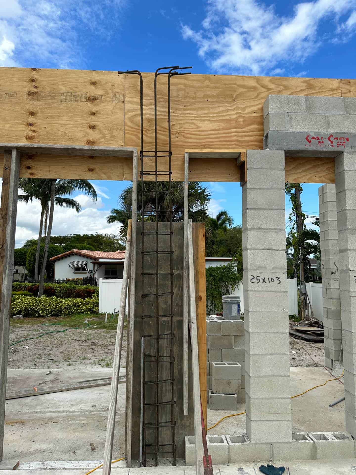
Colum cages are created and tied to the steel stubs that were poured into the foundation.
The bars are bent up top to ‘hook’ into the horizontal beams.
Horizontal beams are tied to the bent bars from the columns.
‘Stirrups’ are used to tie together beams & columns & reinforce the concrete.
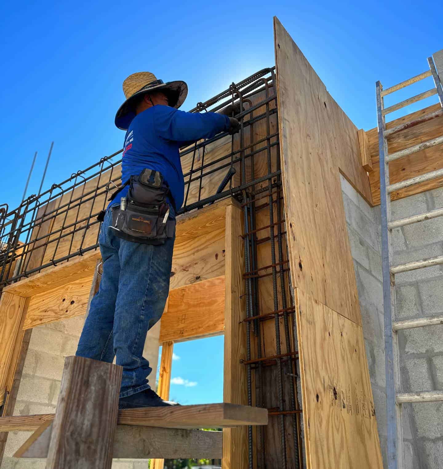
Reinforcing framers tie all the steel together so it stays in place during the concrete pour.
Each bar is a specified size, placed in a specified location within the beam, and is tied together with ‘stirrups’ of a specified size and spacing, all per the engineer’s plan.
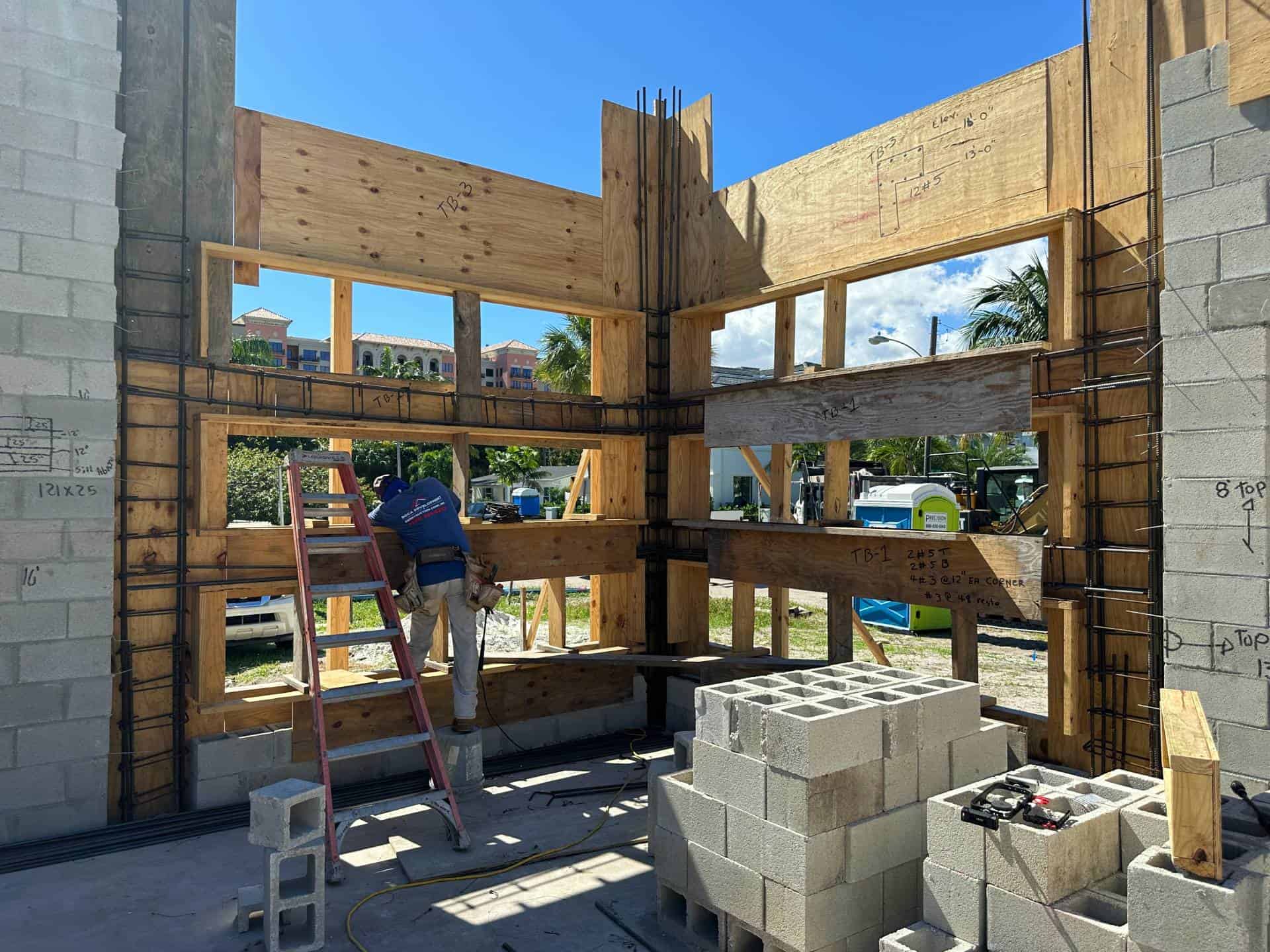
Time Sequence 3: Second Floor Support Beams
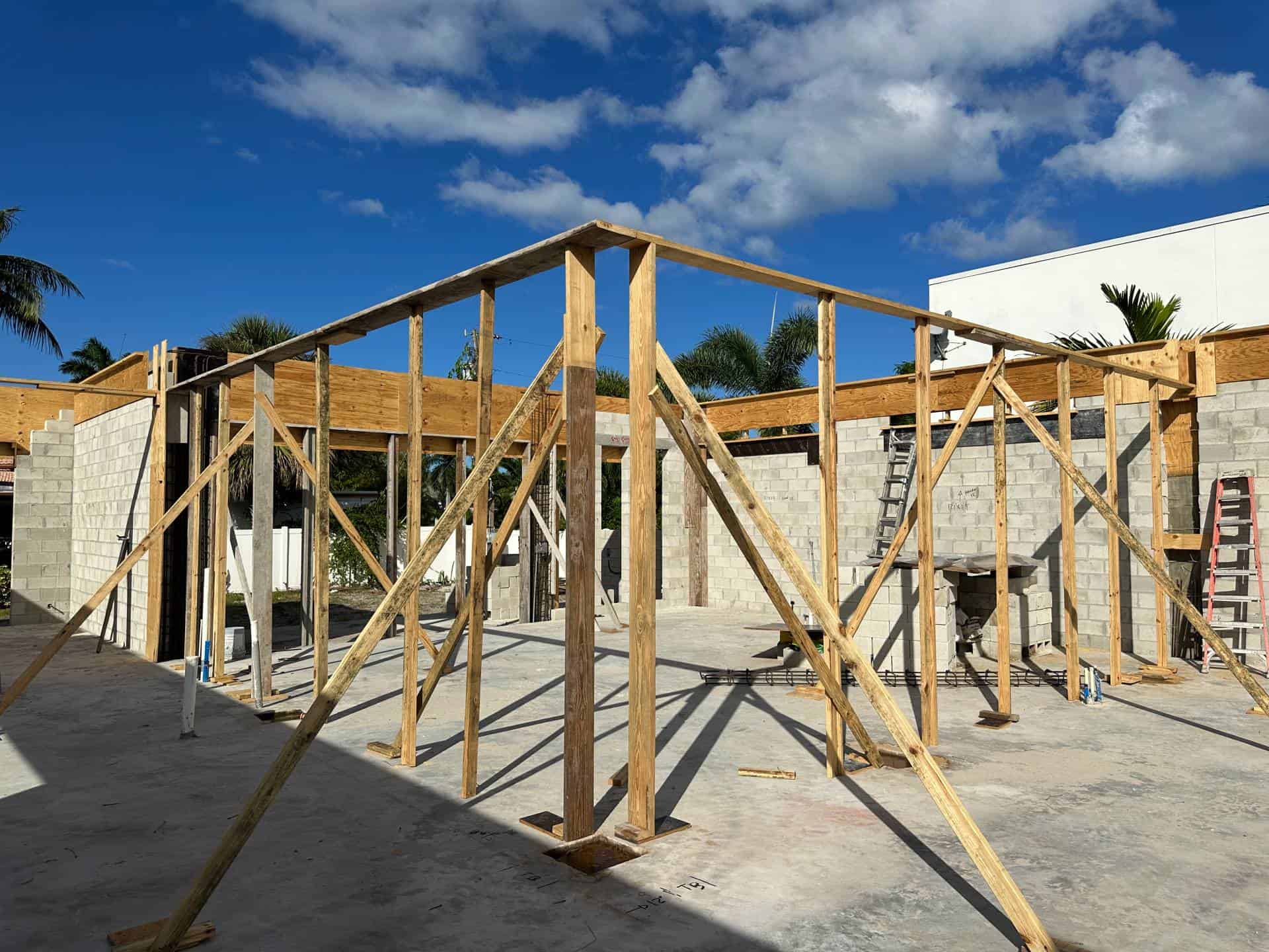
Framing begins to form out a beam that will sit inside the first floor ceiling and hold up the second floor walls.
Framing become formed boxes with the required steel reinforcing.
Steel is stubbed upward to prepare for the second floor masonry walls, just like the foundation.
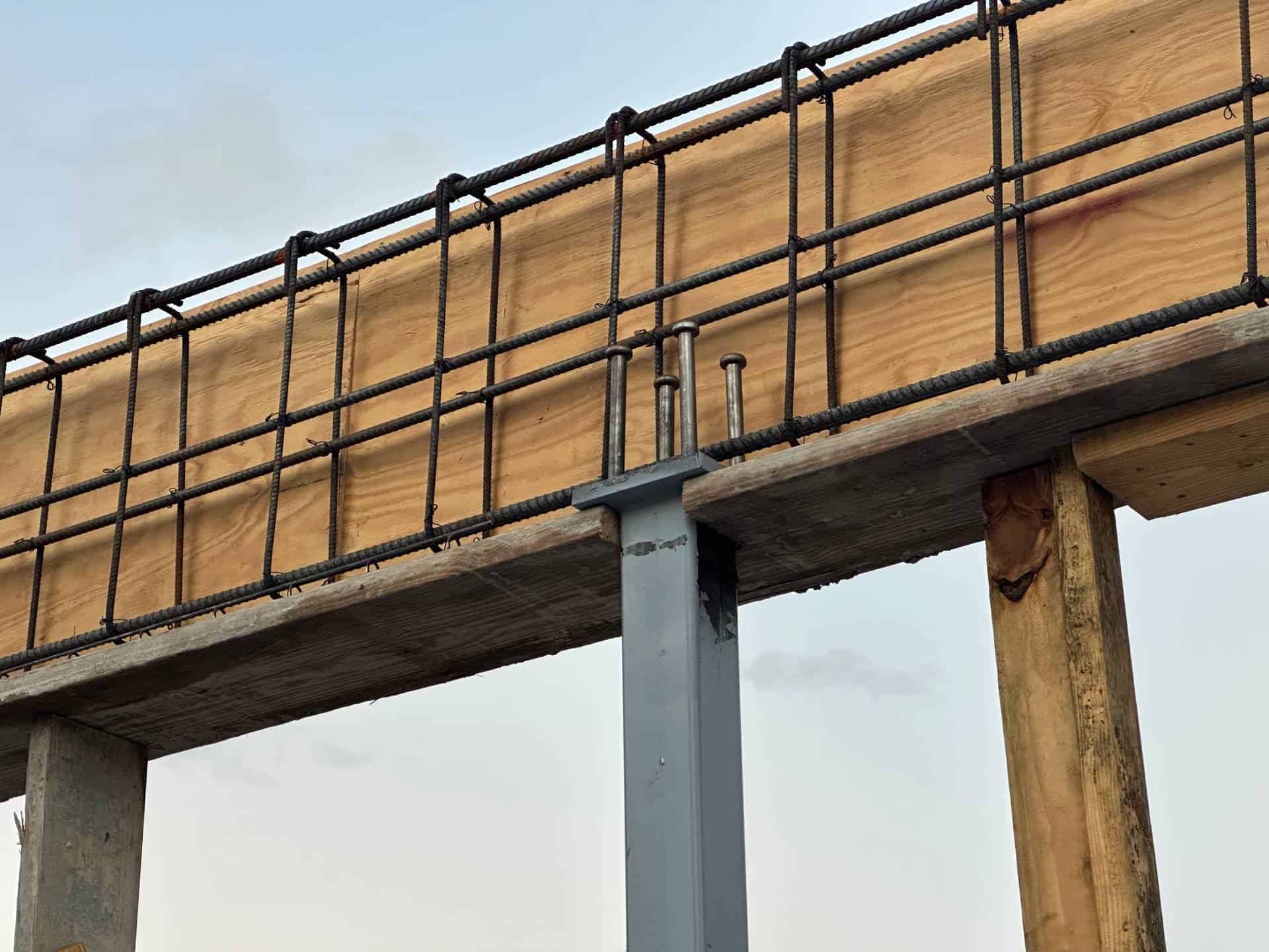
Steel columns (in gray) are added which will hide inside first floor walls to support the beams above. They go atop the foundation pads from Episode 1.
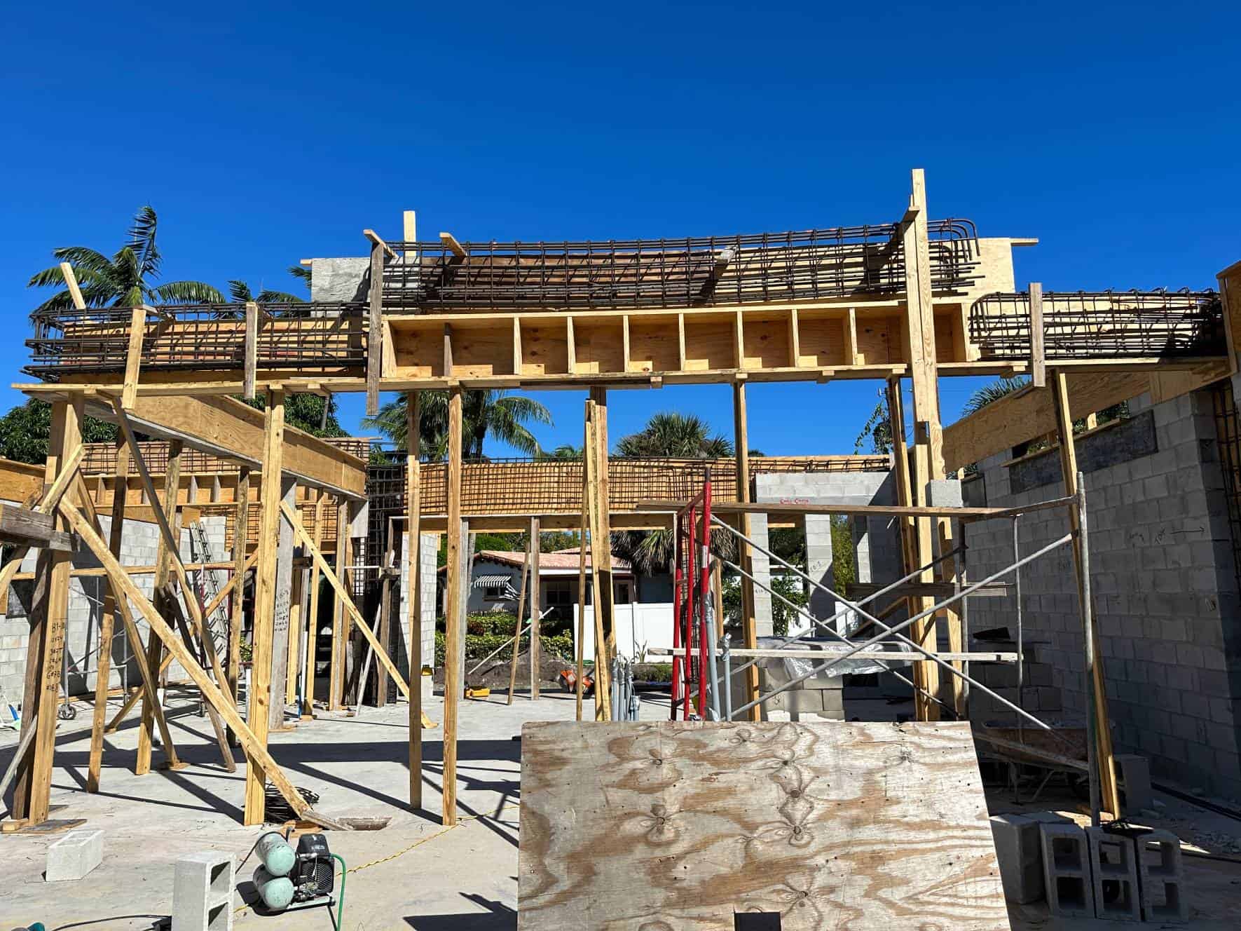
The concrete formwork for this second floor beam is complex – it must rise up and over a portion of the house to frame a portion of the roof since this is only partly a 2-story building.
Close-Up
More about the parts that make up the masonry walls. Press photos to zoom in.
Here you see how the vertical column steel is tied to the steel formed during the foundation pour. The ‘overlap’ is a specified length per code. See more in the technical plans below.
Close-up of the column steel forming into the reinforced concrete beam above. See how this is done in the episode video & description of the steel in the technical plans below.
Close-up of the steel column framing into the concrete beam above.
The steel column is held in place with ‘Nelson Studs’ (named in 1939 after the inventor Edward Nelson) are welded to the steel column top plate to hold it in place after the pour.
Looking down at a typical window sill.
These are poured solid with concrete and have steel reinforcing to help hold the windows in place.
Technical Corner - Plan Tutorial
The Engineering Behind The Plan
Learn to read the construction plans
Plan Page: Beam & Column Schedules
1: Detail showing the steel lap between foundation steel and wall column steel (filled cell shown here). Laps are typically expressed in multiples of bar diameters. For example, a #5 bar lapped 48 bar diameters is 5/8″ * 48 = 30″.
2: As complicated as the steel framing looks is a matching detail specifying exactly how long to lap steel reinforcing & where it’s placed.
3: Each column and filled cell has a detailed schedule showing the number & bar size as well as the stirrups that tie them together.
4: The same applies to each beam. Beam size, top, middle, and bottom steel sizes are specified, & size & spacing of beam stirrups.
All of these beams & columns are calculated by the structural engineer to carry the highest possible loads they can face in the worst of conditions with a code-specified safety factor.
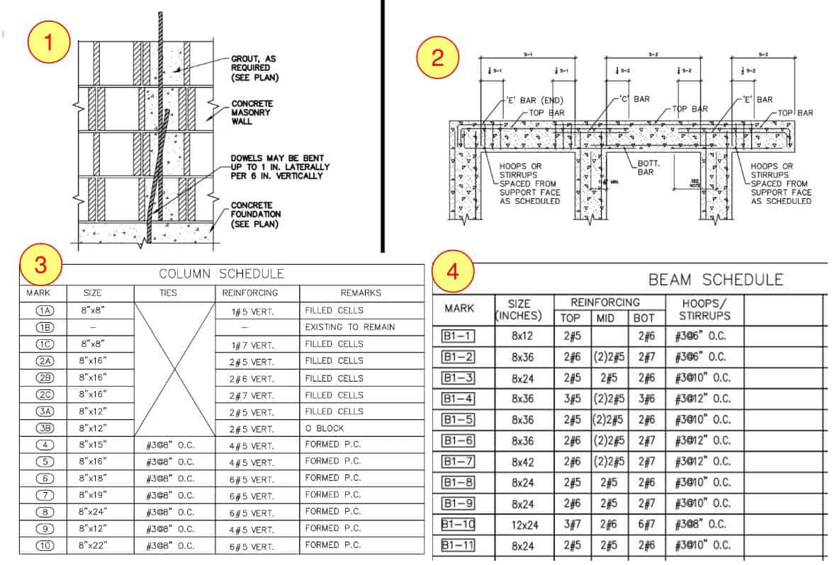
The Engineering Behind The Plan, explained: Bar sizes are in eighths of an inch – a #5 bar is 5/8″ in diameter.
P.C. is a poured column. A ‘mark’ means to look for that column mark on the respective plan. See the foundation plan on Episode 1 for example.
Quick Clips From The Field
Watch the tie beam and tie column framing take shape.
So Where's the Concrete?
The concrete pour is next. Steel reinforcing has to be inspected by building officials and approved, and all formwork has to be checked to make sure it can hold the concrete and not leak out.
With so much to take in here, the concrete pour deserves its own exciting episode. Here’s a link to Episode 3.1 – The Concrete Pour.
