
Up, Up, & Away
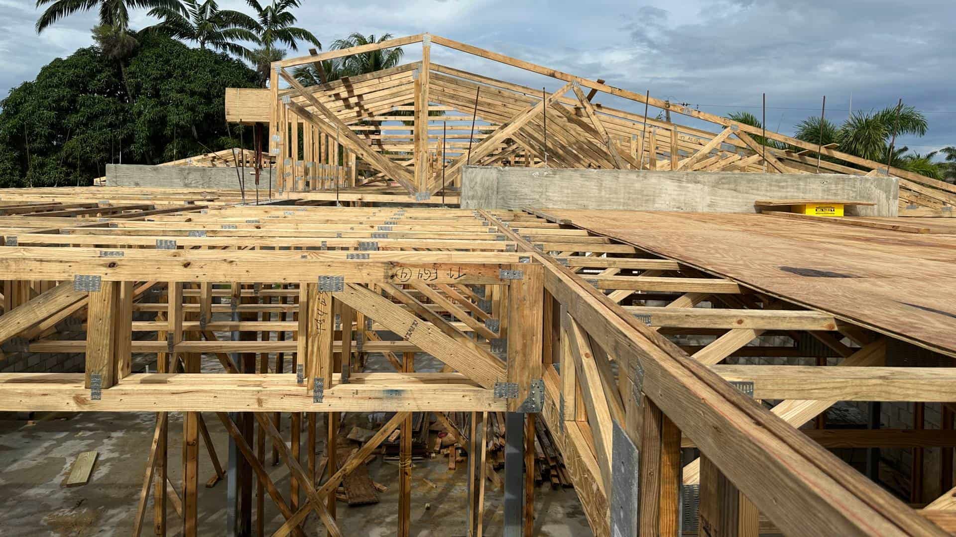
As soon as the first floor tie beam – tie column concrete cured, it was time to get to work stripping the forms & installing floor trusses. A portion of the house is single-story, so some of the roof trusses were installed in this phase as well.
Below we break down the installation. We also filmed dramatic drone video of the progress from high above. Read on, & press/click any photo to enlarge.
The Ledger Beam
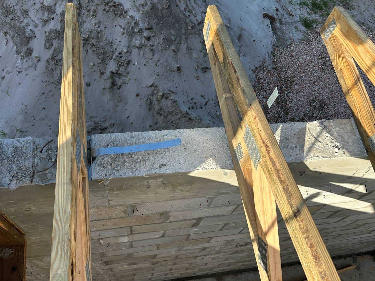
Since this is two-story masonry, there has to be a place to mount the second-floor trusses. A ledger beam does that.
There are several ways to mount floor trusses. Some sit on top of the concrete beam, some sit on top of the ledger beam, and in this case, these will hang from the ledger beam. This is a decision by both the architect and engineer to maximize ceiling height & second-floor construction.
More information about this is detailed in our close-up corner below.
About The Trusses
The floor & roof trusses are engineered & created off-site to exact dimensions for field installation. We’ll review that in an upcoming episode.
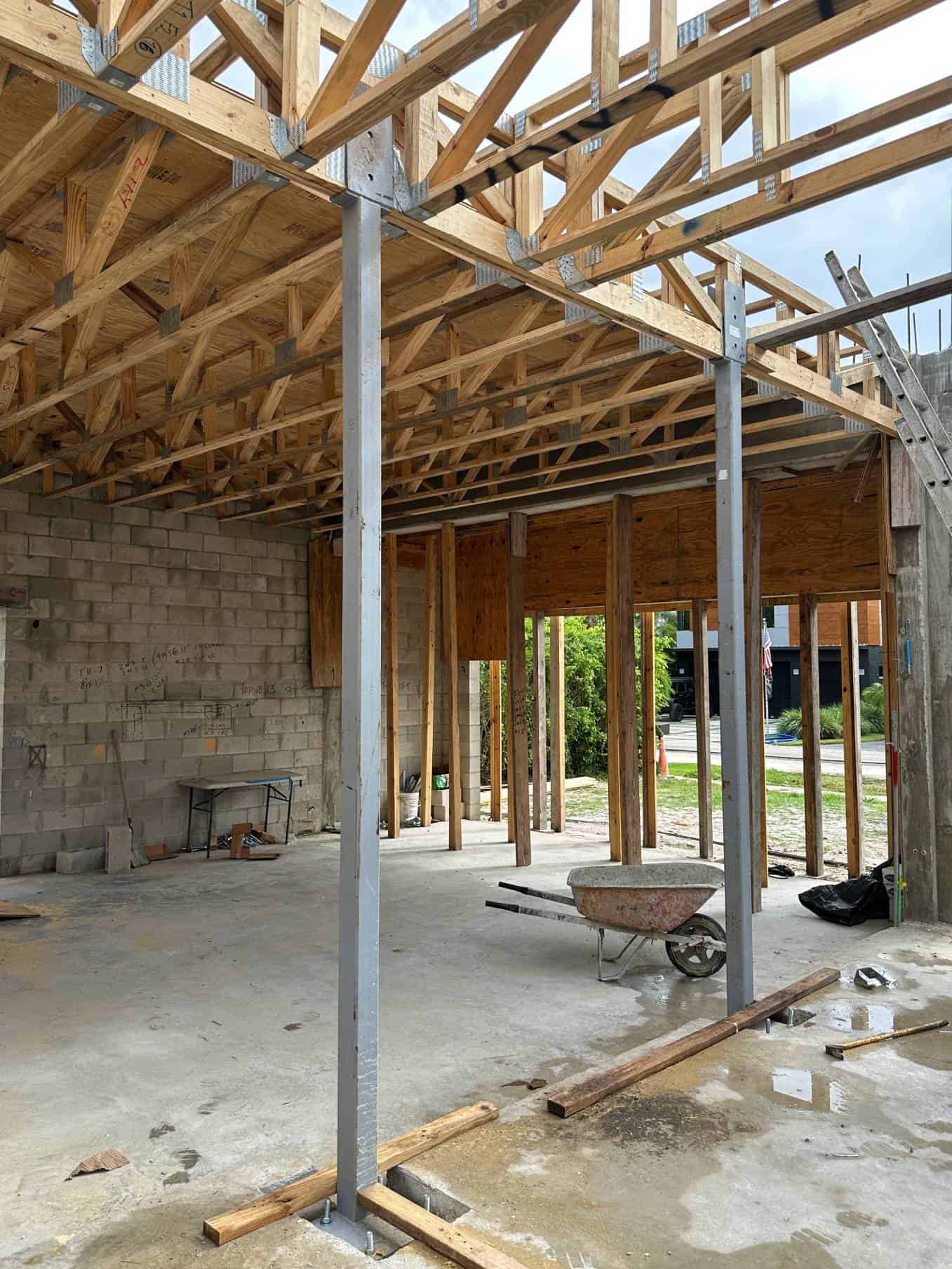
Floor Truss Columns
Hidden in the interior walls of the house will be these steel columns. These are used in key areas to support floor trusses.
These are similar to the steel columns illustrated in our Tie Beam Episode that were formed to concrete beams.
In Episode 1 we showed the indentations in the floor slab that hide the baseplates you see below.
The wood truss buckets are also specially designed to hold the proper configuration of floor truss. In this project, both straight and ‘T’ buckets were used.
In our close-up section below we detail the bucket & baseplate connections and how they appear on the plans.
These are the buckets designed to hold specific areas of the floor trusses.

Roof Trusses Too
Along with the floor trusses, these roof trusses were erected for the one-story portion of the house.
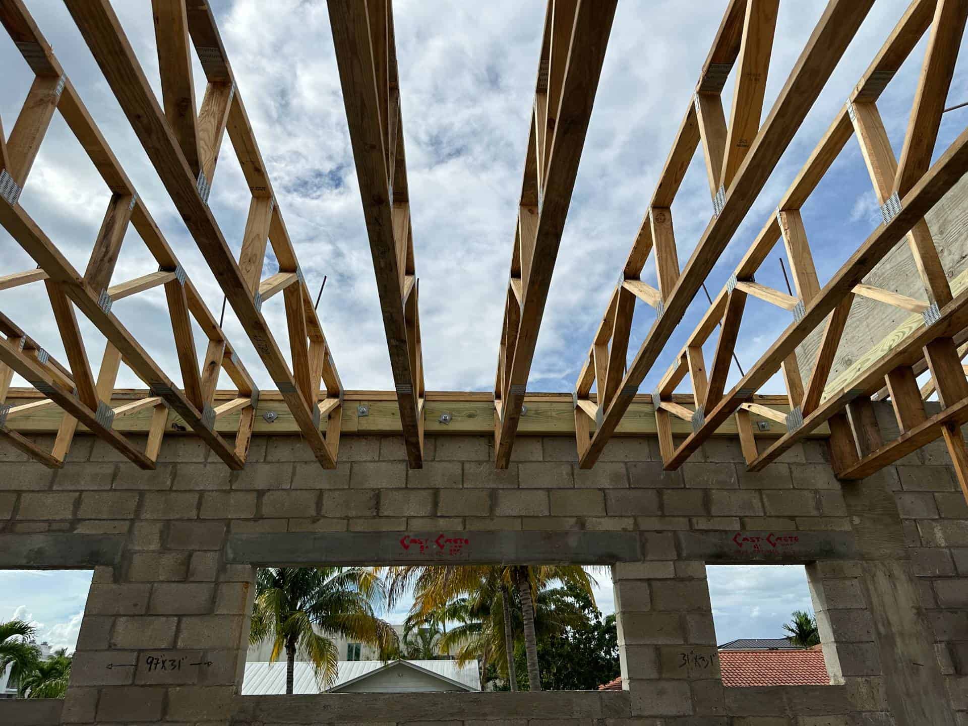
The roof trusses illustrated are unique in that these will be side-mounted to the second-floor masonry wall after its built. A temporary wall was wood-framed below to support them until that’s ready.

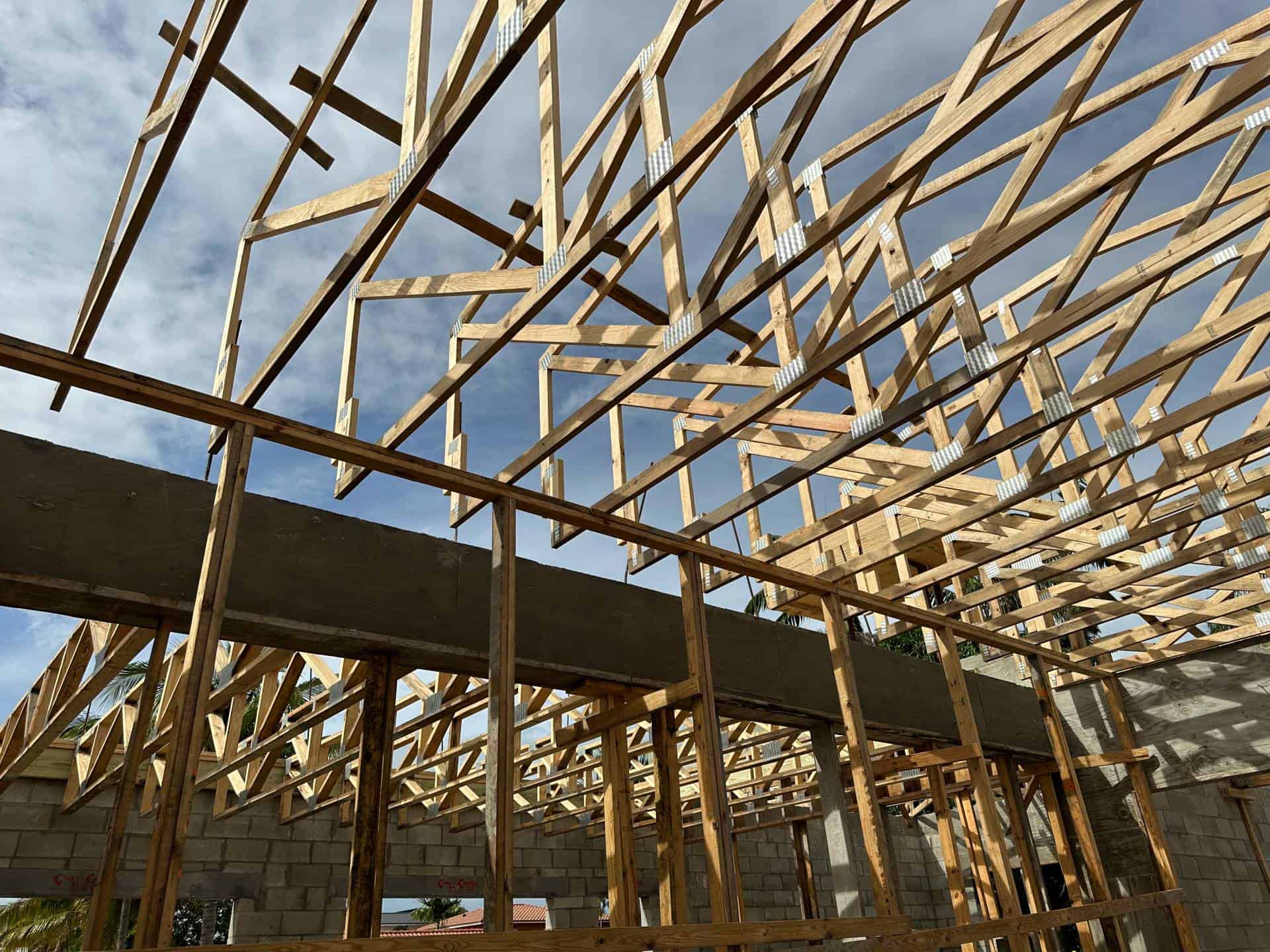
A more conventional means of roof truss installation is top-mounted, where they sit above the concrete beams.
Here you can see the metal straps that were embedded into the concrete beam when it was formed. These will be wrapped and nailed to the trusses to prevent uplift from high winds.
Truss straps used to secure the wood trusses.
Close-Up
Take a closer look at the parts that help construct the second-floor trusses.
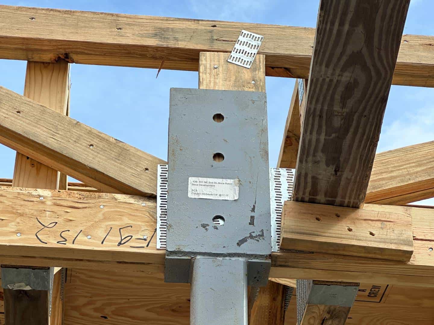
The steel column bucket designed to hold the wood floor trusses. Bolts will be placed in the holes to secure it in place.

The steel baseplate connection. The slab was recessed to be able to hide this connection below the floor tile.

The wood ledger to concrete beam connection. Double 2X10 wood stringers are secured in place using 3/4″ concrete anchors 24″ on center. The floor trusses are then attached to the ledger using metal hangers.
A view of the roof truss straps from above. Half of the strap was embedded into the concrete when it was poured. The strap will be wrapped over the roof truss and nailed per manufacturer specifications.
All Coming Together
Here’s a before & after of the front window area as it was framed and after the roof trusses were formed.
Slide the before/after slider to compare the different construction stages.
Learn more about the before photos from Episode 3.
Here’s another before-after showing the beginnings of the interior concrete beam that’s designed to support both the floor trusses and the second floor.
Slid the before/after slider to compare the different construction stages.
Technical Corner - Plan Tutorial
The Engineering Behind The Plan
Learn to read the construction plans
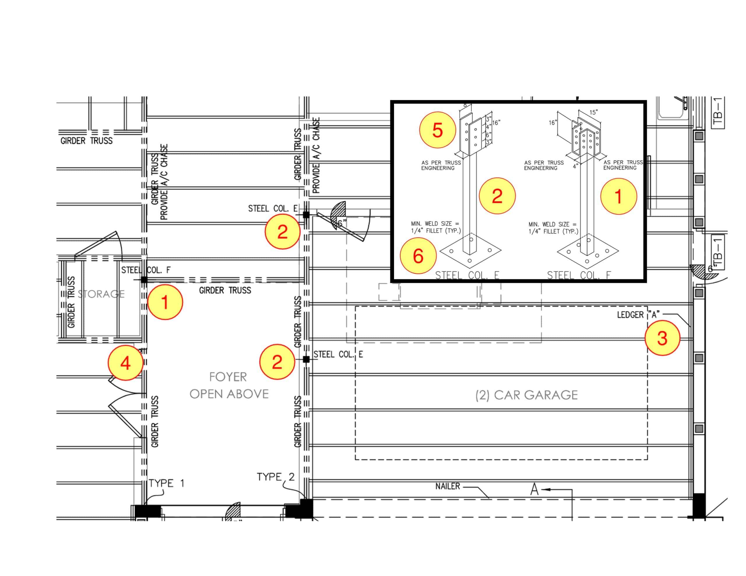
Plan Page: First Floor Trusses
- ‘Steel Column F’ – This steel column is designed to support trusses from two directions. The label ‘Girder Truss’ means that truss is designed to handle additional load, usually from other trusses framing into it or additional loads from above.
- ‘Steel Column E’ – The steel column designed to hold a single-direction truss. Take a look at the photos above to find photos of this steel column.
- Ledger ‘A’ – A ledger is a support beam used to hold additional items, in this case floor trusses. The ledger is called out on the plans to be double 2X10 beams bolted to the concrete with 3/4″ bolts 24″ on center. See this in the close-up above.
- Floor & girder trusses – The girder trusses are shown as 4 or more lines to signify the number of trusses grouped together to strengthen that area. Double lines are just a single truss. Can you find these in the photos above?
- This is how the blueprint calls out the truss buckets.
- This is how the blueprint calls out the baseplate. The connection is detailed in the plan notes.
Floor Truss Blueprints. Click/press the photo to enlarge
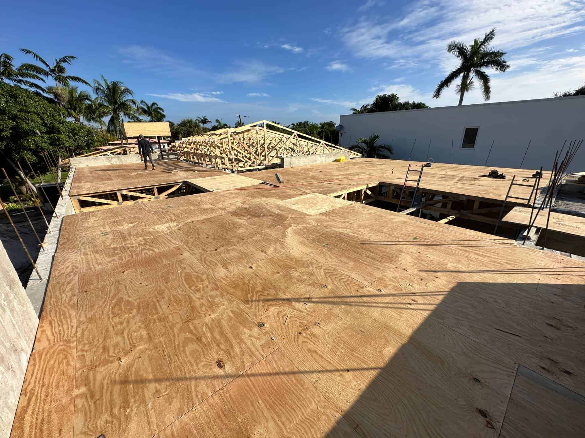
Last Step on The Floor
With the floor trusses in place, a double layer of plywood is nailed in place to form the second floor.
Two areas were purposely left out – One for the stairs and one area to create a dramatic entry that will be visible from above.
The video below provides a perspective of all this taking shape.
Quick Clips From The Field
Take to the skies as we see the floor & roof trusses from above & below.
What's Next?
It’s time to start constructing the second floor walls. Masonry blocks will be hoised up to the newly created second floor and installed similar to the first floor. There are some challenges ahead, stay tuned.
